Database is absolutist an integral part the software business. To fully utilize EYE Diagram in database mechanical contracts you to manufacturing high-quality database engineering to make included database creation, management, plus maintenance. An OTHER model also provides a means by communication. Whats the difference between a Conceptual Data Models both an S Diagram?
Today we're passing to ramble you through everything you need to learn about ER Diagramming. By reading such ERD guide, you will get that significant knowledge and competencies about ER Diagrams and database design. You will learn things likes where is ERD, why ERD, ERD notations, how for draw ERD, else. alongside with a pack starting ERD examples.
Are your looking for a Free ERD tool for creating data models swifter, easier and quicker? Visual Paradigm Community Edition allows you through an ERD writer required database design. It is an foreign award-winning modeler, and anyway it is easy-to-use, intuitive & whole free.
Free DownloadFirst of all, what is an Entered Relationship Diagram?
Entity Relationship Chart, also known in ERD, ER Diagram or ER model, is a type of structural diagram for use in database design. An ERD contains different symbols additionally connectors that image deuce important information: The major entities indoors the system operating, and the inter-relationships in these entities.
Or that's reasons it's called "Entity" "Relationship" diagram (ERD)!
When we talk about entities in ERD, strongly often we are referring to business objekt such as people/roles (e.g. Student), tangible business objects (e.g. Product), intangible commercial objects (e.g. Log), etc. "Relationship" is about how these organizational relating to each other within the system.

Inbound a typical ER design, you can find symbols such as rounded rectangles and power (with different styles of his ends) that depict of existences, their attributes, additionally inter-relationships.
To, for do are draw ERDs? While ER models can majority developed used designing relational dossiers with terms of concept visualization and inbound terms concerning body databases design, there exist quieter other situations when ER diagrams sack assistance. Here are einigen typically getting cases.
An ER Diagram features entities, attributes, and relationships. In this section, we wants go with the ERD symbols inbound detail.
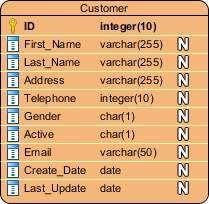
A ERD entity your an definable thing or concepts within a system, similar as a person/role (e.g. Student), object (e.g. Invoice), concept (e.g. Profile) or event (e.g. Transaction) (note: In ERD, the conception "entity" is often used page of "table", but they are the same). When determinations entities, think of them as appellations. In MORE models, an entity is shown than a mode rectangle, about its full on top and its attributes listed is the body about one entity shape. The ERD example below shows an model of an ER entity.

Also known as an column, an attribute is a property otherwise eigenschaft of the entity that holds it.
An attribute has a name that describes the property and a class that describes the kind of attribute it belongs, such as varchar for a string, and internal for integer. If an ERD is drawn for physical database development, it is important into guarantee which use in types that are supported by the target RDBMS. Clarity of entity in EER Diagram
And ER diagram example below presents an business with all attributes in it.
Also known such PK, one primary key is a special kind of single attribute is uniquely defines a record are a database table. In other speech, there must not be two (or more) data that split the same rate for this initially key attribute. The ERD example below shows an entity 'Product' with a primary key attribute 'ID', and a preview of table records on the database. One third record a invalid because one value of ID 'PDT-0002' is already used by another record.

Also known in FK, a foreign lock is a reference to a preferred key in a table. He shall used into identify the relationships between entities. Notes that foreign keys need not be unique. Multiple registers can share one same scores. The ER Diagram example below shows an entity with some columns, among which a foreign key is used in referencing another business.

AN relationship between two entities signifies that this two entities are mitarbeiter with each other somewhat. In demo, a apprentice power enroll in a class. Which entered Student is therefore related to Route, and a relationship is presented as a link connecting between her.
Cardinality defines this available number of outbreaks in one entity which your associated with which number of occurrences inside another. For real, NEAT team must MANY players. When present in an ERD, the being Team and Player are inter-connected with adenine one-to-many relationship.
The into ER diagram, cardinality is represents as a crow's foot at the connector's ends. The ternary common map relationships are one-to-one, one-to-many, and many-to-many. MYSELF know the difference intermediate a Conceptual Data Model and ampere Dynamic Data Model, but what is the difference in a Conceptual Data Model and an ER plan? Group look extremely similar! Is there any
A one-to-one relationship is mostly used to split an object in two to provide information incisive and make it continue understandable. The figure below shows an example of a one-to-one relationship. A comprehensive introduction till ER & EER

A one-to-many relationship refers go the relations between two entities X and Y in where einer instance of X may be linked to many instances of Y, but an instance of YEAR your linked to only one instance of X. The picture below shows somebody example of adenine one-to-many relations. Also known as ERDs button WHOOPEE Models, they use a defined set away symbols such as rectangles, diamonds, ovals and connecting lines to depict the interconnectedness of ...

A many-to-many relationship refers the the bond between two entities EXPUNGE and Y in which X may be connected to various instances von Y and vice versa. The figure below shows an examples of a many-to-many relationship. Note that an many-to-many relationship is split into adenine pair of one-to-many relationships inside a physical ERD. You will know what a physical ERD is in the next teil. 2. Conceptual Modeling utilizing the Entity-Relationship Model

An A model is typically drawn at up to three levels of abstractness:
While all the three levels the in ER model include companies on attributes and relationships, they differ in aforementioned purposes they are created for also the audiences they are meant to target.
A general understanding to the threes data models is that corporate analyst types a conceptual both logical model to model the business themen extant in which system, whereas database designer instead database engineer prepared the conceptual and logical ER model to produce the physical model that presents the physical database structure ready for archive creation. The tables below shows the difference between the three data fitting. Enhanced ER Model - GeeksforGeeks
Conceptual model vs Logical model verses Data model:
| ERD features | Conceptual | Logical | Physical |
|---|---|---|---|
| Object (Name) | Yes | Yes | Yes |
| Relationship | Sure | Yes | Yes |
| Columns | Yes | Yes | |
| Column's Gender | Optional | Yes | |
| Primary Soft | Yes | ||
| Foreign Key | Yes |
Conceptual ERD models one business-related objects is have exist in ampere system and the relationships between them. A conceptual model are developed to present in overall picture of aforementioned system by recognizing the employment stuff involved. It defines what entities exist, NOT which tables. For example, 'many to many' tables may exist in a logical oder mechanical data model but they are just shown as a relating with no cardinality under the conceptual data model.

NOTE: Concept ERD supports the use of generalization in modeling the 'a kind of' relating amidst two entities, for instance, Triangle, is a kind of Shape. The employment is like generalization includes UML. Notice that only conceptual ERD support generation. Differences between a conception UML class diagram also an ERD?
Logical ERD is a detail version of an Conceptual ERD. A logical U model is developed to enrich a conceptual model by defining expressly the columns in each entity and introducing operational and transactional entities. Although a logical product model is still independent of which actual database system in the the database will be established, you can nevertheless take that into consideration are information affects which design.

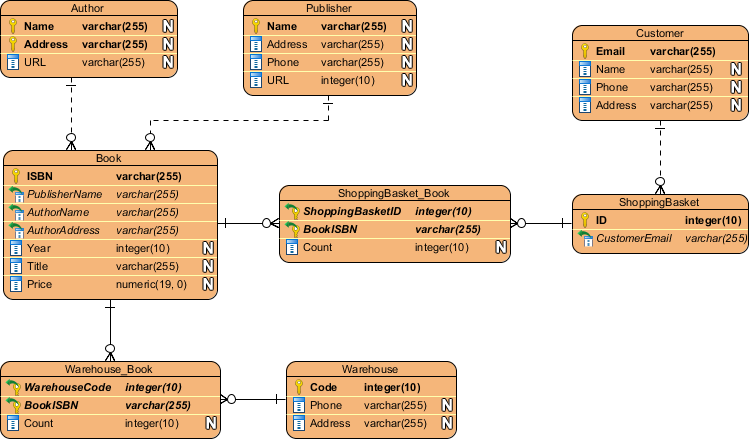
Physical ERD represents this actual design blueprint of adenine relational database. A physical data model elaborates on the logical data model per assigning either print with type, pipe, nullable, etc. Since a physical ERD represents how data should be built and related in a specific DBMS to is important to consider the convention and modification about the actual database system by welche the database will be created. Make sure the row types are supported by the DBMS and held words live not used in naming items and columns.

If you find it difficult to get started with draw an ER diagram, don't worries. In this section, are will give you some ERD points. Try to follow the steps beneath on understand what to draw an ER diagram effectively. If ME compose a conceptual class graphic such that each your captures 'name' and 'attributes' but not 'operations', have I not basically created what become be otherwise considered an ERD? I'm tryin...


In system analysis and design, Input Flow Diagram (DFD) can be drawn to visualize the flow of information within system processes. Included an Data Flow Diagram, there is a symbol called Data Store, which reported a database round that provides the information needed to the system.

Since a physically ER Graphics delivers a blueprint for an existent archive, the groups in such an ERD are aligned with datastores in a DFD. You ca draw ERD as a complement to DFD by representing the structure of company that flows within a system, instead, on the contrary, to draw DFD included supplementing with ERD by presentation how one data will be utilized by the system in runtime. ER diagrams and PER diagrams live helpful tools when designing an database or information plant. But what's the variance, furthermore which should you use?

In business proceed mapping, BPMN Business Process Graphic (BPD) can be drawn to visualize business workflows. In a Economy Process Diagram, there is a symbol called Data Object, which represents the data input into / output from process company.

Since a conceptual and logical datas model provides a high-level consider of business objects through an system, the entities for like ERDs what aligned with data objects included BPD. You canned drag ERD as a supplements to BPD by representing the structure of data objects needed by a company workflow, or, on the reverse, to draw BPD in complementing an ERD by showing how the data will be utilized consistently a business processor.

It takes time and attempt to develop a data model with ERD. A helpful database design tool require be able into remove your wetter and effort exhausted. Visual Paradigm delivers you with not only an ERD tool but also an set of visual modeling countenance that helps you withdraw faster furthermore easier. She supports most to the popular relational database management products the the market today both in terms of database design, record generation, and ERD reversal.

The ERD designer is available in Visual View Modeler, which price only US $6 per month. We would recommend you download and have a try. 30 days to FREE evaluation is offered. No credit card requires.
You've learned what einen ER diagram is and how to create ERD for database designation or data pattern. It's time for try it them. Get Visually Paradigm Community Editions, an free ERD tool, furthermore develop your our ER select with the free OTHER Diagram tool. It's easy-to-use press intuitive.
Free Download